VDMA Standard
Verband Deutscher Maschinen- und Anlagenbau e.V. (Association of German Machine and Plant Construction) is a German engineering association which publishes industry standards.
The VDMA guideline standards are used to describe the floor levelness and flatness in a defined movement VNA.
Although Face can check compliance with the VDMA guidelines, we do not currently endorse the recommendations as they have yet to be validated and peer reviewed.
The Specification
The VDMA Guidelines have three properties of surface regularity:
Table A.1 Limiting values of ZSLOPE
| Top beam level (m) | ZSLOPE (mm/m) | dz = Z x Zslope |
|---|---|---|
| 15 | 1,0 | Z x 1,0 mm/m |
| 10 | 1,5 | Z x 1,5 mm/m |
| up to 6 | 2,0 | Z x 2,0 mm/m |
Table A.2 Limiting values along the tracks
| Distance between measurement l | Gap under straight line t |
|---|---|
| 1m | 2mm |
| 2m | 3mm |
| 3m | 4mm |
| 4m | 5mm |
Table A.3 Limiting values of Fx or Fx, avg
| The values of FX or FX avg Waviness Numbers for all wheel tracks and all 2m sections shall exceed the values given below | |
| Top beam level (m) | Fx or Fx,avg |
|---|---|
| 15 | 525 |
| 10 | 400 |
| up to 6 | 300 |
1.Transverse
The elevational difference in mm between the centres of the front load wheels of the forklift truck.
2. Longitudinal – In accordance with DIN 15185
The longitudinal property of DIN 15185 is derived from the DIN 18202 specification being based around a straight edge of variable lengths.
3. Longitudinal micro small wavelength – ‘Fx’ number.
The VDMA Guidelines have a surface regularity property that controls a micro short wavelength of the floor profile. This property controls the rate in change of slope over two elevation readings 50mm apart to fractions of a millimetre.
The device or ‘Fx’ meter incorporates 9 wheels on three axles and each wheel being 40mm diameter. The wheels are made of steel and the edge is tapered to a width of 0.5mm.
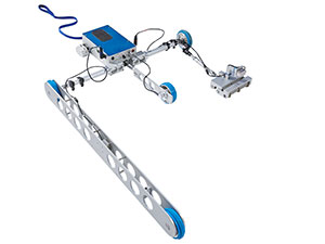
Face Digital ‘Fx’ meter

Photo 1: Face Digital ‘Fx’ meter – 40mm diameter wheels tapered to 0.5mm wide at rim.
Rate of change readings are taken every 50mm of travel down the wheel tracks and an ‘FX’ number is calculated from 38 such readings (total distance travelled being 2 metres). Every 2 metres travelled, an ‘Fx’ number is calculated for each wheel track. The higher the ‘Fx’ number the smoother the floor surface.
Test Instruments:
It is recommended that a continuous method of measurement should be adopted in all cases of defined traffic movement.
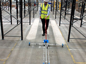
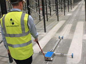
For continuous measurement, the Face DIN Profileograph is used. The DIN Profileograph is a self propelled wheeled instrument which travels along the centreline of the VNA aisle taking continuous measurements both transversely and longitudinally as it does so. The DIN Profileograph is
adjustable so that the skates run in the wheel tracks of the front load wheels of the MHE.
These readings are generated by the three sensors, which are set up to measure the longitudinal and transverse properties of the specification. These readings are collected on a data logger and are subsequently downloaded to a PC where our software generates the graphic traces and compliance results.
For the Longitudinal micro small wavelength measurement or ‘Fx’ number the Profileograph is fitted with the ‘Fx’ meter.
Related Documents
Face Digital DIN 15185 Profileograph

Face Digital DIN 15185 Profileograph for Longitudinal and Transverse measurement.
Profileograph fitted with ‘Fx’ meter
Face Digital DIN 15185 Profileograph fitted with ‘Fx’ meter (VDMA) for Longitudinal micro small wavelength (‘Fx’ Number) measurement.
Measurement Standards


TR34 3rd Ed Chapter 4
The Concrete Society’s TR34 Free Movement (3rd Ed) Chapter 4
(Previous Version)*
† Replaced 2021. New version has no flatness requirement.
